Tailed Hopping Robot: Tail Energized Hopping and Hopping Orientation Control
Abstract
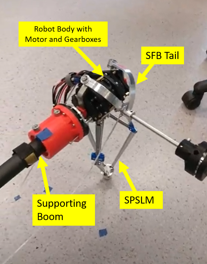
The first monopedal tailed hopping robot was designed to be powerful and capable of agile manoeuvre. It has a 2-DoF Spherical Five Bar (SFB) tail design with Spatial Parallel Spring Leg Mechanism (SPSLM). The SFB tail is driven by 2 motors coupled with 25:1 reduction gearboxes, allowing it to have 2-DoF motion (tail pitch and tail yaw). The SPSLM is driven by a single motor with 49:1 gear ratio, allowing the leg to swing forward and backward. The robot body consisting all the gearboxes and motors weigh only 1kg, and it has a 0.3m tail with 0.25kg mass at the end of the tail. The SPSLM is 0.3m long and weighs only 0.3kg.
The lightweight design of the robot, together with the long compression range of the SPSLM and powerful SFB tail design, large amount of energy generated by the tail inertial force can be stored in the leg during the leg compression phase, allowing the robot to achieve a maximum jumping height of around 15cm.
In the initial study, the robot was able to hop forward and backward continuously and stably by only using the inertial force created by swinging the tail. Remark: The robot is anchored to a supporting boom to decouple the hopping and body orientation control problems, so that we can focus the study mainly on how we can use the swinging tail as an inertial generator to transmit the energy into the SPSLM for stable hopping. However, the high gear ratio leg pitch motor does not favour the use of natural dynamics during stance phase. If we want to pursue hopping orientation control, it is recommended to reduce the gear-ratio of the leg-pitch motor to a point that it is easily backdrivable by its body weight during stance phase.
Tail-energized Jumping Height Test
Tail-energized Stable Planar Hopping Test

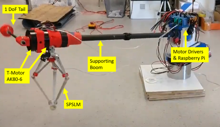
In our next study, we designed a simplified monopedal tailed hopping robot with 1-DoF tail and 1-DoF SPSLM leg using quasi-direct drive motors with single stage planetary gear (gear ratio = 6:1) to further understand the dynamic behaviour of the tailed hopping robot. The robot is designed to have comparable parameters as the previous version. The robot body consists of 2 motors (T-motor AK80-6) and weighs around 1.2kg. The tail has a length of 0.3m and a mass of 0.25kg is attached to the end of it. The SPSLM is 0.3m long and weighs 0.5kg.
Similar study was performed on this robot with the robot anchored to the supporting boom to decouple the hopping and body orientation control problem. With lower gear ratio on the leg pitch motor, we found that the robot can hop more stably and continuously than before. Moreover, we can also control its hopping velocity easily using Raibert Stepper controller.
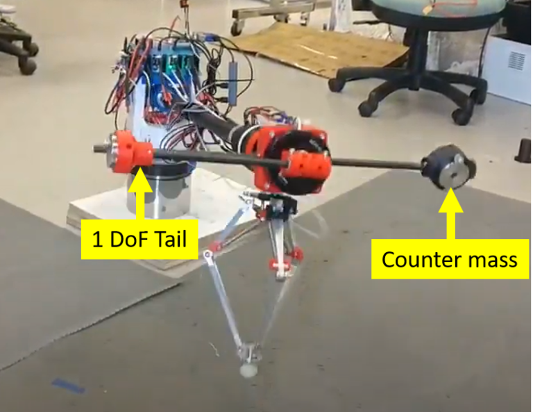
In theory, we have performed many simulations and verified that our controller can offer stable tail-energized hopping motion with hopping orientation control simultaneously. However, in practice, we found that the destabilizing effect created by the gravitational torque of the long tail to be very significant and pretty hard to compensated or offset by the counter-torque created by the leg pitch joint during stance. The robot become very sensitive to initial conditions and parameter tuning. It forces us to include a counter mass to suppress or eliminate most of the destabilizing effect to facilitate the implementation of the hopping orientation control.
Tail-energized Hopping Simulation

Tail-energized Stable Planar Hopping Forward and Backward
Tail-energized Planar Hopping at around 1.5m/s
Based on our experience, it is almost impossible to achieve the orientation control even if the leg pitch joint is back-drivable. Therefore, a counter mass of 0.25kg was added at 0.3m (same length as the tail) in front of the robot body to shift the robot center of mass towards the hip. By having the robot center of mass near the hip, the ground reaction force and the robot gravitational force will not create a torque on the robot. Without the counter mass, the ground reaction force and the robot gravitational force will always create a torque on the robot, causing the robot to exit the stance phase with non zero angular momentum. In theory, it is possible to cancel out this non zero angular momentum by swinging the tail the opposite direction such that the whole system has zero total angular momentum. However, in practice we found it difficult to implement this while simultaneously pumping the energy into the leg to facilitate the continuous hopping of the robot.
Moreover, the counter mass also increases the robot body inertia and helps to increase the inherent stability of the robot body as it reduces the robot angular velocity during flight phase in case the robot exits stance phase with non zero angular momentum. As the tail also needs to reposition to its zero position during the flight phase to prepare for its energy pumping on the next touch down, higher body inertia will allow the robot to maintain its body orientation better as the total angular momentum of the system is conserved during flight phase. In simulation, the robot leg is always assumed to be massless such that swinging the leg during flight phase will not affect the robot body orientation, which is not the case in practice. Hence, the increase of body inertia using the counter mass also causes the leg swing motion during flight phase to have less effect on the robot body orientation.
The robot has a counter mass installed in front the body to offset the destabilization effect due to the gravitational torque of the long tail, otherwise stance phase leg pitch joint controller will not be sufficient to stabilize the orientation during stance. The robot was able to hop stably forward and backward while maintaining its orientation.
Tail-energized Hopping with orientation control

Publications
[1] J. An, X. Ma, C.H. Lo, W. NG, K. W. Samuel Au, “Design and Experimental Validation of a Monopod Robot with 3-DoF Morphable Inertial Tail for Somersault,” IEEE Transaction of Mechatronics, 2021 (under review).
[2] X. Chu, C. H. David Lo, C. Ma, and K. W. Samuel Au, “Null-space-avoidance-based orientation control framework for underactuated, tail-inspired robotic systems in flight phase,” IEEE Robotics and Automation Letters, vol. 4, no. 4, pp. 3916–3923, 2019.
[3] K. W. Samuel Au, et al., “Morphable inertial appendage, systems and associated methods,” US Provisional Patent, US 62/810,258.
